
A 4010 End Fed Half Wave, EFHW, antenna in a slope is hands-down my go to field antenna. It works, pretty much anyway you can get it up. I didn’t figure this out with a modeling software, I figured it out during the last 500 Parks On The Air activations.
What I’ve missed in my trial-n-error method of learning is that there are some significant strengths and weakness to the 4010-S system. The relationship between the wave form and the earth greatly influences the radiation pattern. A 40m transmission will behave very differently than a 20m transmission, on the same wire.
Today, any Joe Schmo with a PC can model antennas and analyze the radiation patterns. Well, Joe Schmo has a better memory than me because I’m challenged to remember where the money spots are.
What follows is a quick-reference guide we can peruse before we head out in the morning. We can even bookmark it on a phone and peek at it from the field when we’re picking a table and tree.
These models are of a 4010 EFHW Sloper, up 30ft, and fed from the ground. A quick note about antennas and modeled gain: The gain predicted by the model is a comparison to a theoretical, isotropic radiator (an antenna that radiates equally in all directions in a perfect sphere). Our “wire in a tree” results will be different – but will likely parallel the visuals below.
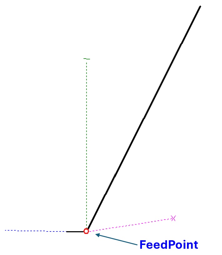
All values reflect radiation at 15 degrees off the horizon and as a control to align our perspectives, the 1/4 wave vertical yields about -1 dBi at this takeoff angle.
The frequencies modeled are in the center of each illustration.
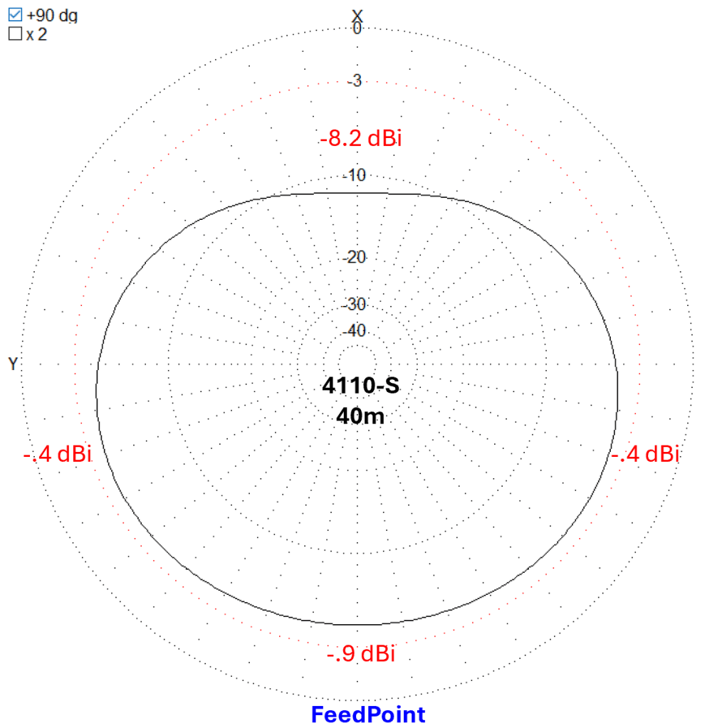
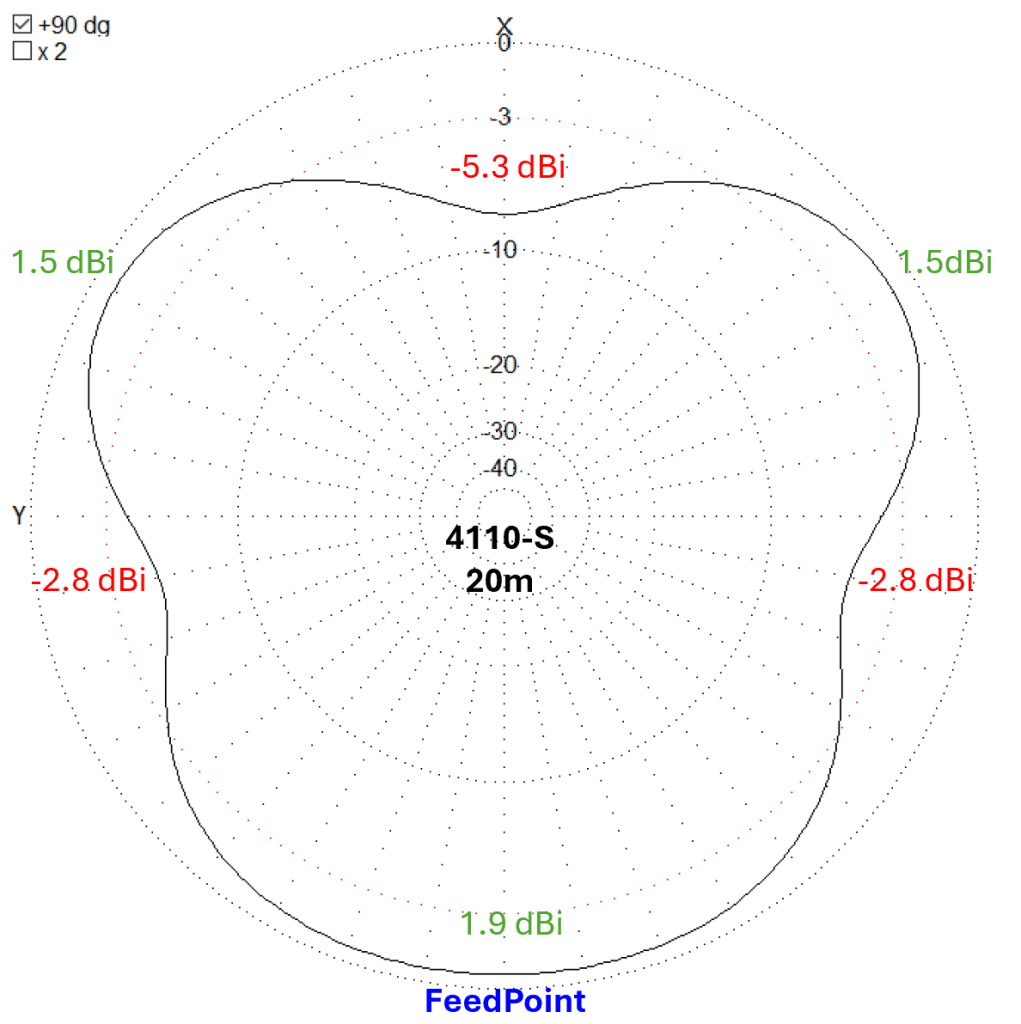
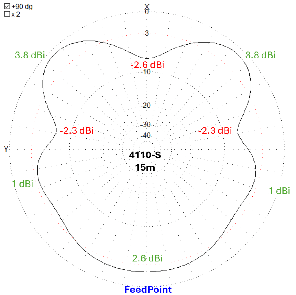
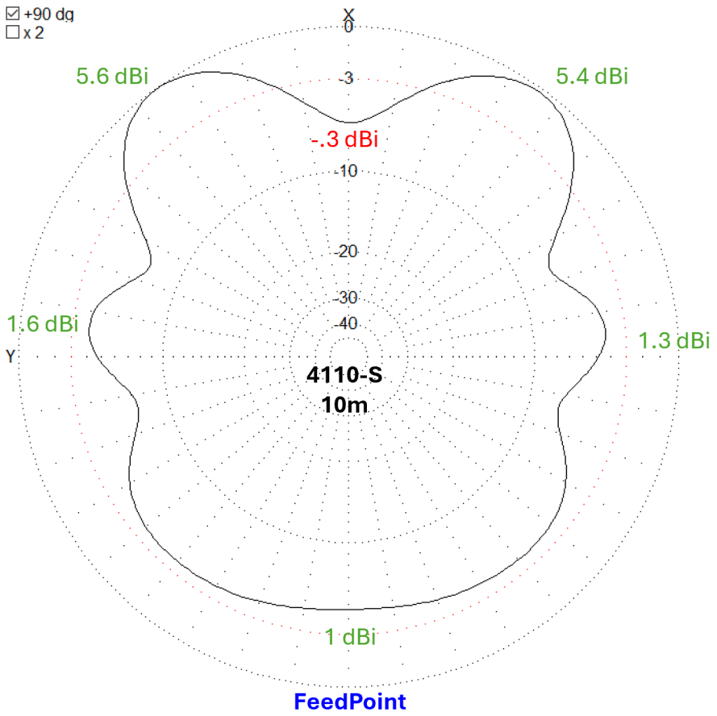
So, let’s put this whole thing in perspective. We’ve all used a 1/4 wave vertical. We’ve made tons of contacts on it. We know if anything can work today, a 1/4 whip will do it. Know what the gain looks like at 20dg above the horizon? -.5 dBi. That means your 100 watts of yackity yack is attenuated. Not by much, but the gain is a negative value. That’s the baseline perspective when you look at the charts above. The ol’ 4010 ain’t so shabby now, eh?
In all honesty, the radiation patterns of the four different bands can start to look like a Rorschach Test, so I’ve made a little crib sheet. You can right click on the illustration below and save it to your phone. That way you always know which way to face the feed point on your 66 foot wire.
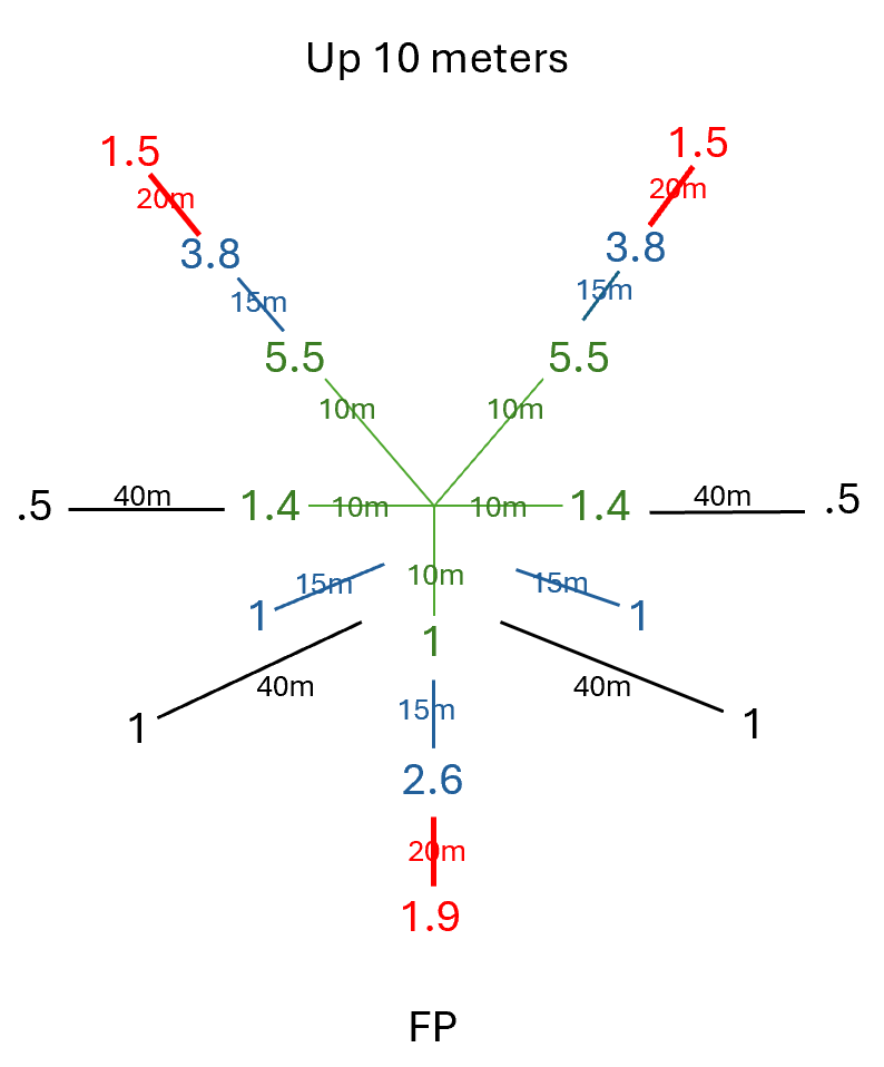
I’m not going for a groundbreaking presentation here. Just something useful for /P operators. Hope you find it so.
TNX ES 73
KA5TXN
DitWit


Leave a Reply