I’ve been playing at modeling antennas. It’s an on-and-off again thing where every time I play with the software I get a little closer to understanding it. I use MMANA-GAL to model. It’s free. It’s also fairly simple if you invest some time noodling with it. DX Commander, Callum, has some very decent tutorial-type videos on YouTube.
Before we go any further, it’s critical to accept and occasionally remind ourselves that we’re talking about antenna models, not antennas. These models can give us insight into relative performance, like lobes or nulls in a system’s radiating pattern that influence directionality. The models also allow us to draw some comparisons between systems, like between a dipole and a vertical.
The actual performance is subject to the deployment – the conditions in the field and how we get them up. Performance depends on these variables, plus the variables on the other end of the QSO. It’s impossible to make assumptions about who’s up and hunting or the performance of their station.
Back to reality. For resonant wires, I use a 40m-10m EFHW and a 20m EFHW. I get one end up on a mast or in a tree, slope the wire down and put the 49:1 transformer and feed point on or near the ground. In my mind, the 40-10 EFHW is the baseline for portable antenna performance.
I cut a wire for a 20m simply for convenience sake. Being a shorter wire, it takes less room. Plus, the solar cycle takes us to 20 meters for real work right now; everything else is just candy. I’ve never given much thought to comparing performance between the two. …until yesterday.
My 20m EFHW rocked CW on 20 meters. I called CQ once then called QRT about 15 minutes later with 15 QSOs. Even with the delays of pileups and struggling with calls, the conditions still brought me 15 QSOs in 15 minutes. Not all that remarkable, but it just seemed like every things was really working compared to the last few activations.
Is there a performance difference between the 20m and 40m EFHW or were there just more hunters listening? So, let’s look at some models.
14.050Mhz through a 40-10 EFHW
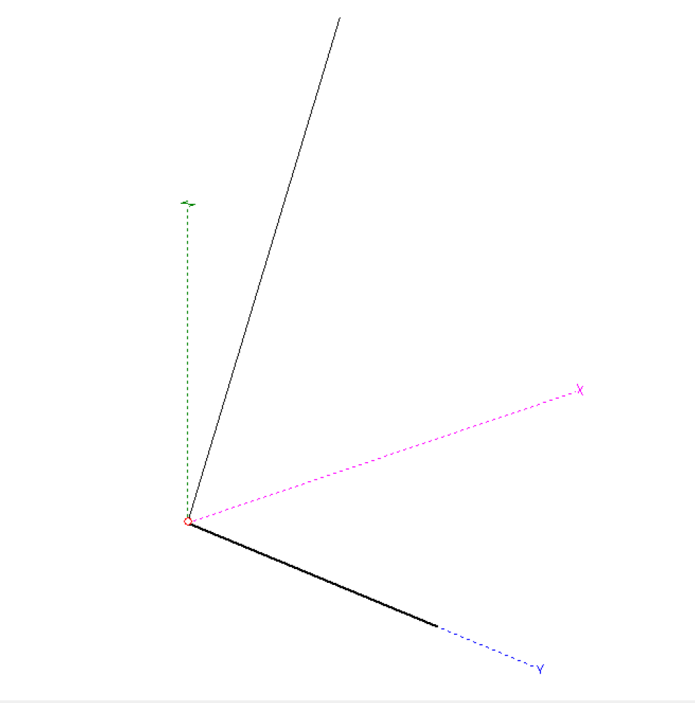
The illustration below shows a 19.9m radiator configured as a sloper and running along the X axis. The feed point is at ground level with about 25 feet of coax feedline. Note: Unless you put a choke at the feed point, the shield of your feedline becomes part of the antenna circuit.

Calculated for 20 meters, the model plots like this:
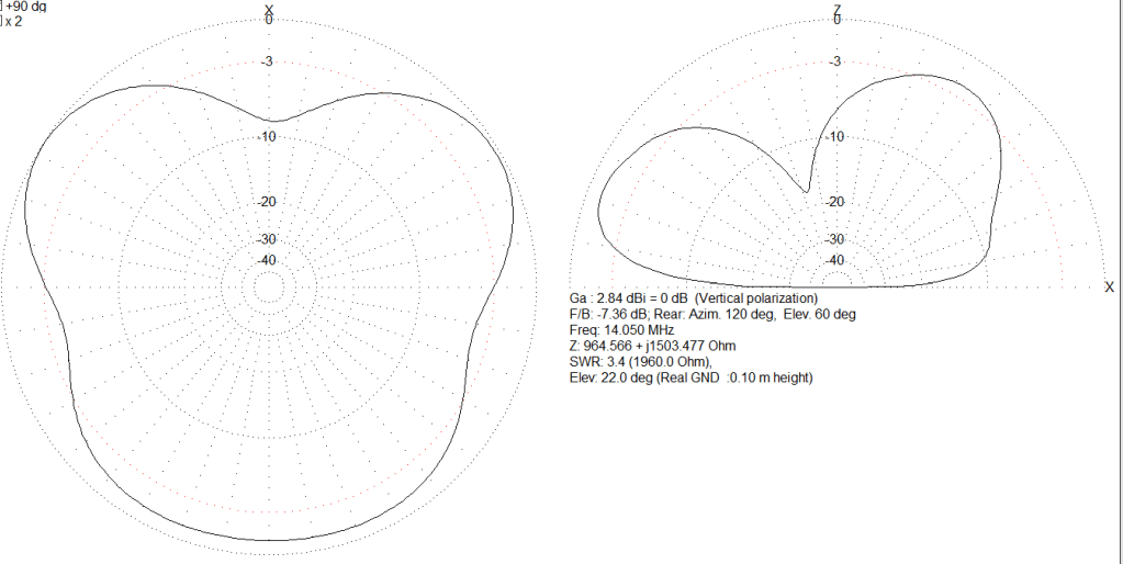
The plot on the left is a top-down look at the radiation pattern. Like a bird’s eye view. The one on the right is an elevation view, a crosscut of the pattern as seen from the side. Remember, the wire of the sloper is on the X axis so the top of the top-down plot is the mast, the bottom is the feed point.
The Micky Mouse ears on the left plot are called lobes, and that dip between them is called a null. Lobes are bulges of radiation, nulls are dips of less radiation. The lobes calculate to about 2.6 dbi of gain. So yay, we get some gain.
The plot on the right shows the gain relative to the horizon – radiation takeoff angle. In this system, max gain (1.9 dBi) plots at about 40 degrees off the horizon, in the direction of the mast.

A 3D plot shows this a little better. I’ve put a little smidge of yellow highlight on the end of the wire where it’s secured to the mast. (on the right)
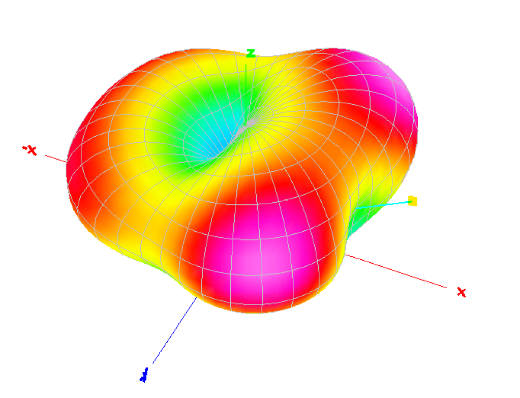
Now, I’ve always been told that an EFHW, like a Dipole, is practically omnidirectional with a little more strength to the sides. That’s not what this model shows. It shows the primary radiation from front to back, away from the feed point. And, two lobes on either side of the radiator, branching off a 45 degrees.
But remember, this is a model, not an antenna system. And models are drastically affected by frequency and height. Very interesting, none the less.
14.050Mhz through a 20m EFHW
The illustration below shows a shorter, 10.835 meter radiator and the same 25ft coax feedline. The radiator is fed from the ground and in in a slope, up to a 10 meter mast.
This 20m EFHW models without any lobes or nulls. Shown in the illustration below, it does radiate more strongly towards the front, meaning towards where the wire is attached 30 feet up in tree or mast. Notice, there is 4.2 dBi at this highest radiation point.

Again, with a little smudge of yellow pointing out the radiator, this antenna models as almost omnidirectional with 4.2 dBi towards the front and 3 dBi to the rear. While there is more gain to the front, there is real gain in all directions.

Further, the gain has DX punch with 4 dBi at the horizon and 3 dBi at 15 degrees off the horizon.

Conclusions?
Again, these are models, not antennas….. But it’s interesting. First, it’s not a sure thing to generally declare the EFHW radiates to the broadside like a dipole. Second, the 40-10 wire is directional with 20m for me to notice it. I definitely need to start noting the bearing of my wire in my activation notes to compare it to my QSO map.
I enjoyed putting this together. I know this data would be much easier to evaluate if certain “key” fields were side-by-side in a table. Sorry, maybe next time.
I think I might add some verticals to the mix. Let me know what you think.
As always,
TNX ES 73
KA5TXN
DitWit

Leave a reply to KA5TXN Cancel reply