W5DRT and I bought NanoVNAs and I don’t know about Dave, but I’ve been testing everything that doesn’t bite or slap.
So playing with this little gadget, I’ve profiled SRW through several transformer into a known resistive load. More fun, I’ve done lots of fiddling with the LOGMAG function where it compares gain between two ports to determine what leaked – for ham radio, we use it to measure insertion loss.
The RF noise at home is horrendous. I slipped a home made messy choke between an LDG RU 1:1 and my rig and Great Ceaser’s Ghost, it works to filter out noise! There’s still noise, but I can resolve much of it with a finger on the RF gain.
But I wonder if I could do better – and have just the toy to find out.
I built two messy chokes, one from a FT240-31 and another from an FT240-43. The 43 mix seems to be the assumed “go to” for all HF applications, but I hear and read about the 31 mix from more than one YouTube Elmer.
The Question: Should I use 31 instead of 43?
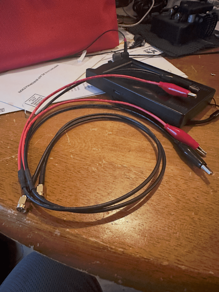
I took a trip down the Amazon and picked some 31 and 43 toroids and some short RG-8X cables. I also dropped by DigiKey for two pair of alligator clip test leads I could use with the VNA – and also ordered some 100ohm resistors to make load standards to work with the alligator clips.
So I collected the data and can show you the table and chart now, but what’s the fun in that? There’s allot more to it, but if you need an answer now –
- Mix 43 gives more attenuation, but either will get it done.
- Neither work for 10m. Put the LDG in series to attenuate 10m.
- Making a real choke with solid core wire and bifilar wraps may offer better performance.
Now that the cheaters are gone, on with the project. Moving on.
The goal:
Use VNA LOGMAG to measure gain losses as attenuation for each choke on 80, 40, 20, 15, and 10 meters.
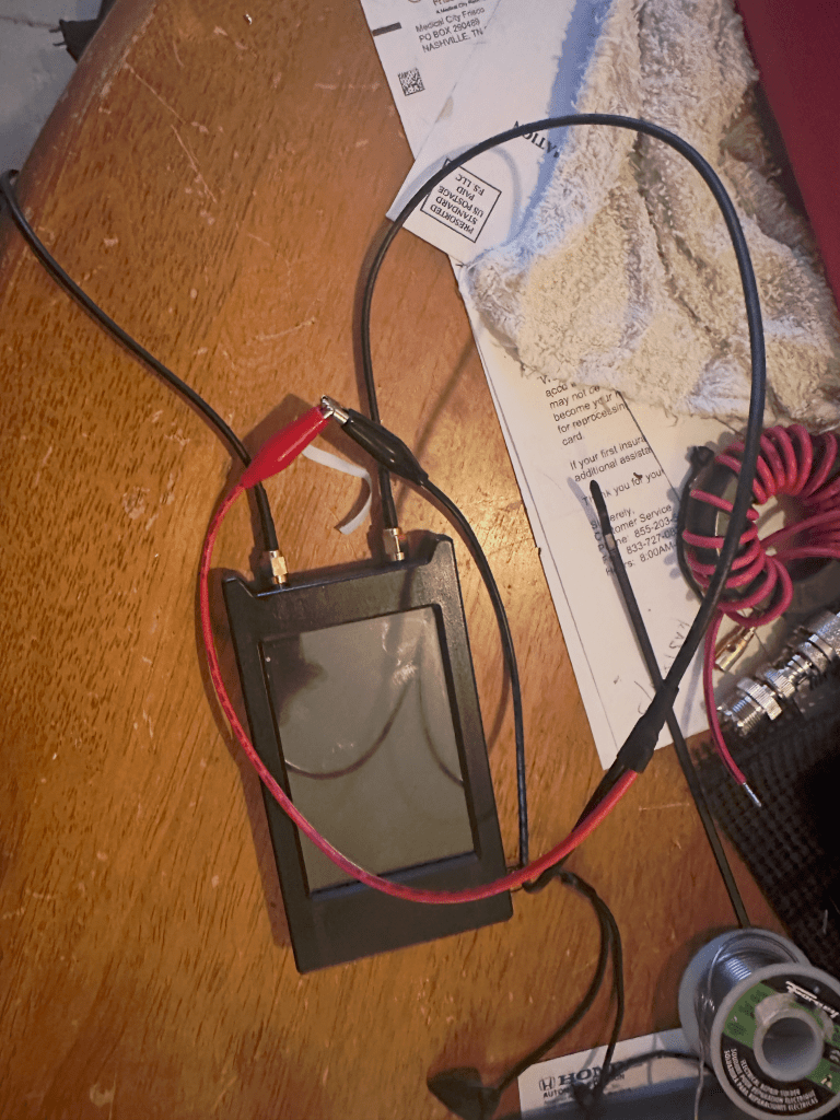
The bench:
(Terminology) A test bench is a controlled, often simulated, environment used to evaluate the performance, functionality, and reliability of a product, software, or electronic component (the Unit Under Test or UUT) before it reaches production. It acts as a specialized, safe and controlled space to run tests in specific, repeatable scenarios.
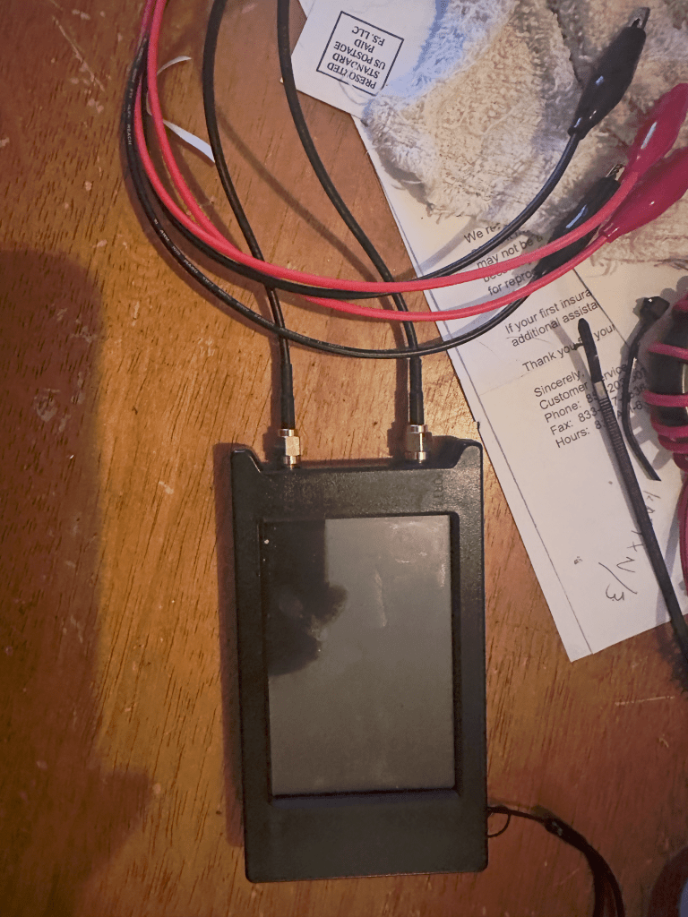
On our bench, we have the VNA, the calibration standards, and the cables. The UUT and the bench are two wholly segregated entities. The bench is a standard that tests the variables of the UUT. It’s important to prevent the parts of the bench from becoming variables in the test.
In our case, measuring loss is the difference between what’s reported sent from one from one port and what’s measured received at a second port. We calibrate the bench to baseline the units and values of measurement between these two ports.
The VNA comes with calibration standards for the ports. There’s a little open cap, a short cap, a load cap, and a barrel connector for measuring thru. It’s critical that everything used to send, conduct, and receive energy is either calibrated with the bench, or is isolated and measured so it can be mathematically eliminated from the results.
Think of weighing something in a cup. You either weigh the cup and subtract that every time to get the actual weight of the contents…… Or put the empty cup on the scale and push the zero button. I chose the latter.
The Calibration:
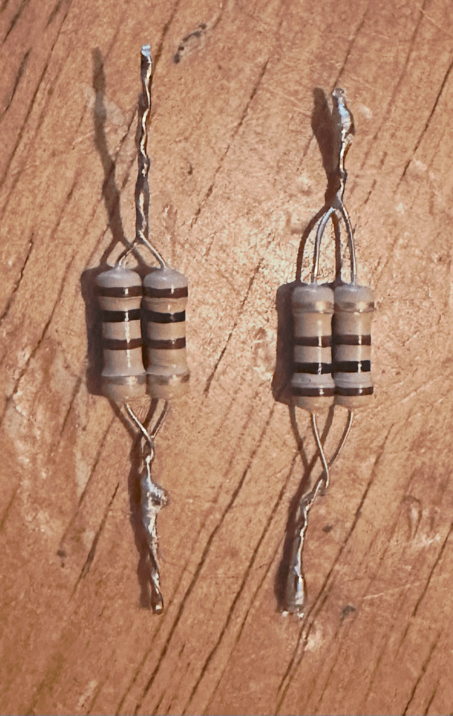
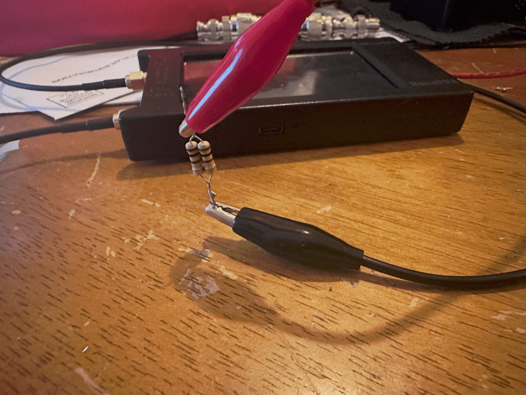
To include the test leads in the calibration, I needed to include them to in the SOLT process (Short, Open, Load, Thru). The little SMA load standard included with the VNA won’t work for alligator clips, so I made some. I made a 50ohm ‘load” standard for the alligator clips by soldering two 100ohm resistors in parallel. They read 50.1 ohm each – close enough.
- OPEN: Leads connected to both ports and not connected to or touching anything else.
2. SHORT: Port 1 red connected to port 1 black.
3. LOAD: Port 1 red and black clips connected to either end of two 100ohm resisters that are connected in parallel.
4. ISOLATE: Same as load plus port 2 red and black clips connected to either end of two 100ohm resisters that are connected in parallel.
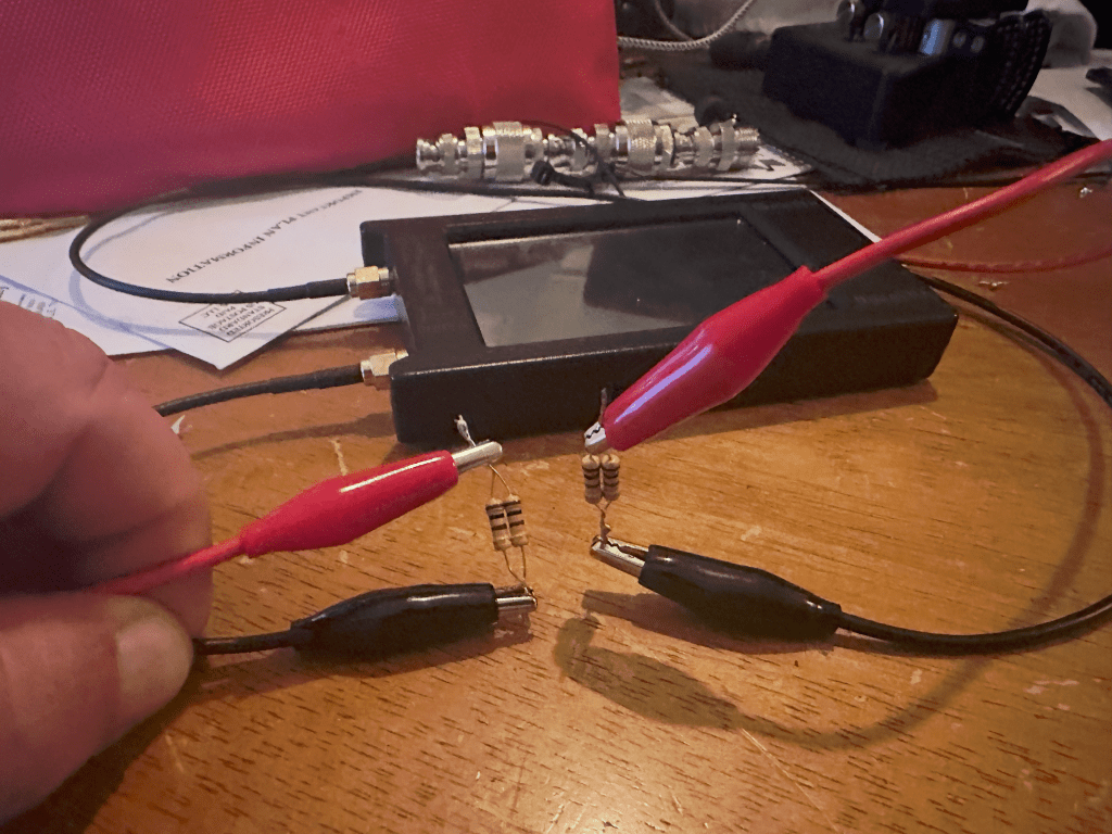
5. THRU: Port 1 red and black clips connected to Port 2 red and black clips. 1 red to 2 red and 1 black to 2 black.
The Test:
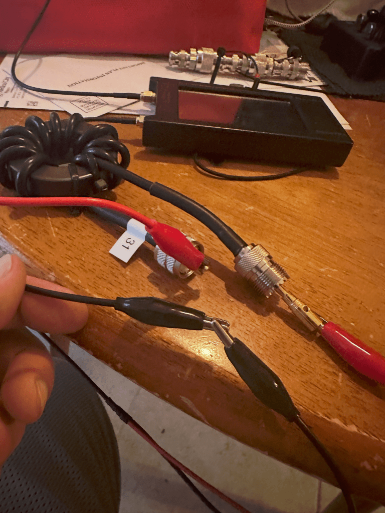
The actual testing is somewhat uneventful. Connect port 1 red to the center pin of the coax. At the other end of the coax, poke a banana plug in the end and connect port 2 red to it. (yes, we could’ve included the banana plug in the THRU step)
Before I show the data, I learned a few things.
- Keep the VNA away from other electrical objects while using it – both calibrating and measuring. This means your phone and laptop.
- Save the calibration to the SD card and give it a good name. There’s no telling what you may eventually want to use alligator clips to logmag.
Results:
| 80m | 40m | 20m | 15m | 10m | |
| Messy 31-11 | 31.27 | 30.79 | 27.98 | 23.49 | 18.62 |
| Messy 43-11 | 29.31 | 32.17 | 30.51 | 23.15 | 16.89 |
| LDG RU 1:1 | 8.94 | 13.99 | 19.26 | 22.64 | 23.66 |
The “-11” indicates 11 turns through the toroid. It’s just how much room there is in a 240 toroid.
The values returned are negative values indicating loss of measured gain. I’m using them to indicate intentional attenuation, so I’m showing them as positive values.
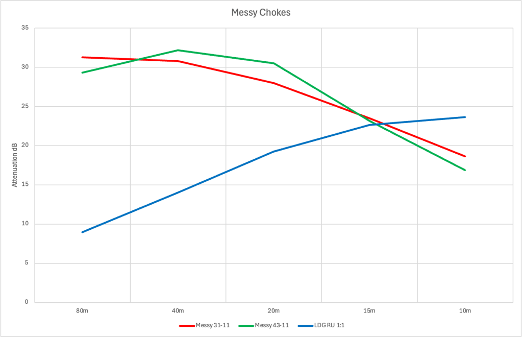
So what’s the resulting conclusions? I’ll run the RU 1:1 and the 43 mix in series. Rather, I have the test data to continue doing what I was already doing but now I know why.
The 43 mix out performs the 31 mix in the portions of the spectrum I frequent and the weakness it shows above 20 MHz is compensated for by using the RU 1:1 in series.
Yes, two common mode (CM) chokes placed in series are generally additive regarding their common-mode impedance, allowing for enhanced noise suppression across a broader frequency range. When connected in series, the total common-mode inductance which creates a higher total impedance to common-mode noise.
So this was fun for a Saturday that’s too wet to POTA! I learned some things and hope you did too.
73 and see you in the park
KA5TXN
DitWit

Leave a comment